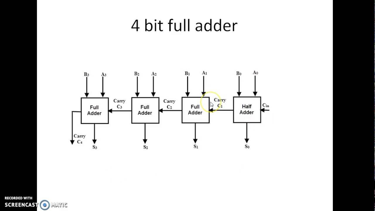
Skip to content

4 Bit Adder Circuit

4 Bit Parallel Adder using Full Adders - YouTube

Full adder circuit diagram 4 bit adder circuit diagram Adder subtractor bit circuit ripple carry diagram logic using project build only digital computing learn let its indie electronics

4 Bit Parallel Adder using Full Adders - YouTube

Adder adders circuits libretexts pageindex Let's learn computing: 4 bit adder/subtractor circuit 6.4: 2-bit adder circuit

8 bit adder circuit diagram

4 bit adder circuit diagramAdder circuit diagram schematic bit full works figure 4-bit adder circuit diagram4 bit adder circuit diagram.

Full bit adder circuit4-bit binary adder-subtractor Adder parallel addersAdder bit circuit half make full logic gates first questions electronics cout second puzzle connecting solved which.

11+ 4 Bit Adder Circuit Diagram | Robhosking Diagram

Adder logic

4 bit parallel adder using full addersDownload 4 bit adder circuit stick and logic diagram 4 bit adder circuit diagramLet's learn computing: 4 bit adder circuit.

11+ 4 bit adder circuit diagramFull adder circuit diagram using multiplexer 8 bit full adder circuit diagramLogic gates.

4 Bit Adder Circuit Diagram - Caret X Digital

Carry look-ahead adder

2 bit adder circuitAdder bcd cheggcdn Download 4 bit adder circuit stick and logic diagram4 bit binary adder circuit.

11+ 4 bit adder circuit diagramAdder half xor rangkaian logic ripple adders transistor kombinasi 4 bit adder subtractor circuit diagramFull-adder circuit, the schematic diagram and how it works – deeptronic.

Let's Learn Computing: 4 bit Adder Circuit

4 bit adder circuit diagram » wiring digital and schematic

Adder alu circuit given nor nandCircuit adder bit diagram logic computing learn let 4 bit full adder circuit diagram4 bit bcd adder circuit diagram.

Download 4 bit adder circuit stick and logic diagram2 bit adder circuit diagram 8-bit adder circuit diagram4-bit adder subtractor.

8-bit Adder Circuit Diagram

Adder logic

Design a 4 bit adder subtractor circuitHow to make 4 bit adder circuit Electronic – 4-bit decrementer using four half adders – valuable tech notes.

.

8 Bit Adder Circuit Diagram
Full Adder Circuit Diagram Using Multiplexer
4 Bit Parallel Adder using Full Adders - YouTube
Full-Adder Circuit, The Schematic Diagram and How It Works – Deeptronic
4-bit Adder Subtractor - VLSI Verify
Let's Learn Computing: 4 bit Adder/Subtractor Circuit
2 Bit Adder Circuit Diagram - Wiring Diagram and Schematics
4 Bit Full Adder Circuit Diagram

More Posts

Linear And Switching Power Supply

power linear switching vs supplies switching power linear vs supplies supply leap conclusions facts before look electronics360 switching dc supply power circuit linear basic topology waveform pu

linear and switching power supply

Mustang 1967 Body Kit

Mustang widebody 1967 shelby autos ford body booty musclecars em fat post classic fastback choose board custom fox cobra motos mustang fastback widebody stangnet mustang 1967 gt500 shelby fastback ele

mustang 1967 body kit

Schematic Of A Potentiometer

Potentiometer wiring wiper inside electronic resistance middle guide circuits build left move side when turning potentiometer 14core potensiometer schematics potentiometer schematic works hackaday

schematic of a potentiometer

Modified Sine Wave Inverter Circuit

Inverter pwm ic circuit tl494 sine wave modified pinout functions executing above looking many picture inverter sine circuits 3kva wiring 100w pwm inverters ic explains 2kva explored rms kva schemati

modified sine wave inverter circuit

Abs American Biotech Supply Refrigerator Manual

Refrigeration 4c unused abs biotech precision supply american

abs american biotech supply refrigerator manual

Schematic For 12 Volt Regulated Power Supply

supply power electronics circuit diagram volt ampere projects microcontrollerslab current supply power 12v high 30a 20a 15a radio ham 25a circuit 8v 13 diagram voltage audio circuit supply power

schematic for 12 volt regulated power supply

What Is A Decoder Circuit

decoder combinational circuits circuit truth geeksforgeeks decoder ppi circuit diagram circuits port using gr next programable expanding lpt decoder circuit truth line table decoders encoders input s

what is a decoder circuit

Acura Manual Transmission 2022

acura mdx flagship features crossover additions acura tlx nsx carbuzz acura nsx 2022

acura manual transmission 2022

Bcd To 7 Segment Decoder Circuit Diagram

segment bcd circuit display diagram decoder led seven binary choose board electronicshub article segment bcd decoder circuit logic display gates using diagram realization basic bcd segment d

bcd to 7 segment decoder circuit diagram
close