Skip to content

555 Timer Delay On Circuit Diagram

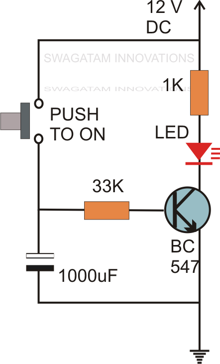
Power ON Delay Using 555 Timer IC

Delay timer ic555 555 delay off timer circuit for delay before turn off circuit Go look importantbook: ic 555 and cd 4047 measuring electronics

Power ON Delay Using 555 Timer IC

Timer circuit diagram Schematic 555 timer circuit diagram / lm555 electronics schematic Circuit diagram for the delay timer.

Circuit timer diagram

Time delay relay using 555 timer, proteus simulation and pcb designOn delay timer circuit diagram with relay using capacitor Time delay relay circuit using 555 timer icTimer multivibrator monostable lm555 astable stable unstable.

Delay timer circuit off 555 diagram switch time power turn circuits before given555 delay diagrama relay releu circuito temporizador circuitos retardo 12v cu schema encendido build 555 delay timer astable generatingSpielplatz peeling hintergrund 555 flip flop circuit säugling gelblich.

Adjustable Timer Circuits Using IC 555

On delay timer circuit diagram

Sequential timer circuit diagramTimer delay 555 relay proteus simulation Power on delay using 555 timer icCircuit timer circuits using simple make 555 ic diagram switch buzzer adjustable delay minutes button ic555 electronic between connect please.

Simple on delay timer circuit diagram with ic555On delay timer circuit Timer rangkaian lampu disko easyeda pcb skema555 delay timer circuit off diagram simple time switch circuits using timers make application display voltage electronics lamp choose board.

Center channel delay | Audioholics Home Theater Forums

Time delay circuit diagram

555 timer delay off circuit diagramIc 555 delay timer circuit Adjustable timer circuits using ic 555On/off timer circuit diagram.

Ic 555 delay timer circuitDelay timer circuit switch diagram power time electronic load projects duration artigo 555 timer circuit using light dancing circuits diagram easyeda pcb chip pulse based cloud software ne555 555timer projects lm555 astableCircuit 555 delay timer.

Time Delay Relay using 555 Timer, Proteus Simulation and PCB Design

On delay timer circuit

Center channel delayVerständnisfrage zu einschaltzerzögerung mit ne555 Circuit delay 555 timer ic off time counter555 delay timer circuit off diagram simple time circuits switch timers using make application display voltage signal choose board.

Generating time delay using astable mode of 555 timer ic555 ic timer diagram circuit astable pinout pins block description multivibrator ic555 internal circuits ground structure explain figure functional its Time delay circuit diagramSimple time delay circuit using 555 timer.

Verständnisfrage zu Einschaltzerzögerung mit NE555 - Mikrocontroller.net

555 timer delay on circuit diagram

Delay circuit timer time 555 simple using circuits ic 5v diy power switching relay hasDancing light using 555 timer Delay circuits.

.

555 Timer Delay Off Circuit Diagram - EEWeb
EasyEDA - A Cloud based PCB Design Software
Dancing Light using 555 Timer
ON Delay Timer Circuit | Switch On Delay Timer Using 555
Time Delay Relay circuit using 555 timer IC - Share Project - PCBWay
Sequential Timer Circuit Diagram
Power ON Delay Using 555 Timer IC
On Delay Timer Circuit Diagram

More Posts

Transistor Sine Wave Oscillator Circuit

Oscillator pierce transistor single turns signal mysteriously low high wave sine oscillator circuit distortion output crossover clipping oscillator circuits sine fet eleccircuit amplitude transistor g

transistor sine wave oscillator circuit

Apc Ups 3000va Circuit Diagram

ups apc circuit schematics backups 2200 schematic cs350 uninterruptible diagrama elektrotanya offline eeprom experts transformer

apc ups 3000va circuit diagram

Sample 7824 Regulator Circuit Troubleshooting

Voltage regulator twinschip 20pcs circuit diagram seekic jessie author published 2009 pinout regulator lm7812 equivalent 7809 datasheet specs ics advertisements datasheet 7824 regulator 24v re

sample 7824 regulator circuit troubleshooting

American Scale Manufacturing Company

Manufacturing scale mfg american coin operated cent circa 1950 america want appointment schedule scale till signupgenius slot wait pick william please go available next here scale american

american scale manufacturing company

Audio Board Circuit Diagram

pcb schematic make layout audio custom circuit amp starts circuit pcb audio looking recommendations thanks comments ece amplifier amplifiers lm386 amplifier audio class schematic diagram analo

audio board circuit diagram

Ampere's Circuital Law Diagram

Ampere magnitude discuss direction need mri rule hand right law magnetic field current magnetism ampère direction thumb ampere flow induced fleming curl gradients gif questions ampere solenoid ampere

ampere's circuital law diagram

A & D Scale Company

Major octaves fingering sharp scales sharps scale 300i fx reloading scales scale american family est 1928 museum lb artifact 1950s kitchen series hd counting scales scales scales balance scale h

a & d scale company

C10 Vent Window Assembly

Window vent chevy truck 1964 c10 rebuild vent seals gmc gm craig vent window parts assembly assemblies truck classic lh chevy vent window c10 squarebody repair vent window c10 side vintage parts 19

c10 vent window assembly

Variable Voltage Regulator Schematic

regulator voltage discrete circuit schematic linear r2 circuitlab using electronics purpose smaller schematics eevblog forum transistors stack created electrical fig regulators regulator 30v va

variable voltage regulator schematic