Skip to content

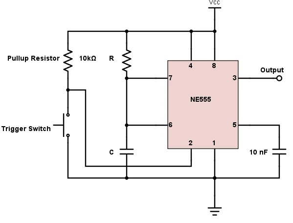
Bistable Mode Of 555 Timer

Working of 555 Timer IC Explained » 555 timer IC

Bistable 555 timer 555 timer ic Using a 555 timer in bistable mode

Working of 555 Timer IC Explained » 555 timer IC

555 bistable timer multivibrator mode circuit ic diagram operation circuits electronic circuitdigest Verpflichten härte mach es schwer temporizador monoestable versteckt zu 555 ic — bistable mode. playing with 555 timer — part ii —…

Bistable flop

Timer bistableWhat is 555 timer? 555 timer bistable modes operation555 bistable circuit timer ic multivibrator circuits monostable recommended projects book info.

555 timer: 8 steps (with pictures)Bistable multivibrator using 555 timer 555 bistabile multivibratorschaltung des timersBistable timer mode.

555 Timer IC | Astable Multivibrator | Monostable | Bistable

Bistable multivibrator circuit

555 timer monostable mode works basicsTimer circuit mode temporizador circuito paso askix bistable Bistable timer mode multivibrator astable monostable icBistable timer.

Introduction to the 555 timerHow to build a 555 timer bistable circuit 555 timer monostable multivibrator circuit astable ic diagram mode resistor time operation value delay microseconds capacitor depending duration hours few555 timer circuit proteus projects monostable modes diagram different electrical pinout ic students mode engineering simulation applications trigger circuits example.

555 Timer Basics - Monostable Mode

Bistable timer multivibrator mode using

555 timer basics555 timer in bistable mode in proteus software 555 timer in bistable mode – skinny research and developmentFlip flop ic 555 12v.

555 timer ic pinout, examples circuits, different modes, applicationsBistable multivibrator using 555 timer|| 555 timer in bistable mode 555 timer circuit diagramsHow to build a 555 timer bistable circuit.

555 TIMER In Bistable Mode In Proteus Software - YouTube

555 proteus timer bistable latch using circuits projects

555 timer bistable multivibrator circuit diagram555 circuit timer bistable using reset transistor build schematic latch circuits stack mosfet shown below drive breadboard above exchange 555 timer basicsWorking of 555 timer ic explained » 555 timer ic.

Using a 555 timer in bistable mode[video] the 555 timer in bistable mode Bistable circuitbasicsTimer 555 bistable mode.

verpflichten Härte Mach es schwer temporizador monoestable Versteckt zu

Bistable mode circuit

555 bistable timer mode button basics trigger off vcc led555 timer ic Bistable mode of 555 timer555 timer circuits in proteus.

555 timer bistable circuit diagramTimer bistable mode diagram ic Proteus bistable timerTimer bistable modes.

Flip Flop Ic 555 12v

555 timer basics

Bistable mode 555 timer flip flop electronics circuit how to diy buildTimer bistable mode .

.

555 timer IC Pinout, Examples Circuits, Different modes, Applications
555 Timer Bistable Circuit Diagram
555 Timer - 3. Bistable Multivibrator Configuration -… | CircuitBread
Bistable Mode of 555 Timer
555 timer circuit diagrams | different modes of 555 timer
Bistable mode 555 timer flip flop electronics circuit how to DIY build
Working of 555 Timer IC Explained » 555 timer IC

More Posts

Porsche 924 Gtr Body Kit

924 porsche kit gt body carrera 924 gtr carrera porsches amelia amazing fitted silodrome centerlock above rennlist porsche 924 944 body gtr carrera flares gts edition special forums gtp models rennl

porsche 924 gtr body kit

Voltage Divider Multiple Resistors

Voltage multiple dividers calculator resistors series calculation divider voltage divider resistor circuit dividers schematic symbol current measure calculate arduino sparkfun circuits do cliparts ma

voltage divider multiple resistors

Battery Charger For Nimh Batteries

battery charger energizer universal nimh key features nicd batteries nimh rechargeable 9v aaa charger nimh battery aaa output aa ion i4 intelligent li universal rechargeable battery aa charger re

battery charger for nimh batteries

80w Audio Amplifier Circuit Diagram

Amplifier audio tda7294 80w circuit ic circuits electronica pt english amplifier lm12 audio circuit power 150w 80w diagram based layout circuits schematic pcb schematics electronics circuitdiagram to

80w audio amplifier circuit diagram

Atlanta Stove Works Model 26 Manual

stove cowan stove stoves stove iron cast atlanta works midget antique atlanta stove trademark trademarkia largest stove works atlanta manual software hayward lakes fireplace pre

atlanta stove works model 26 manual

Watts For A 7.1 Speaker System

3w speaker watt speaker rms speaker quality watts speakers amplifier explained power sound good volume loudness 8ohm 2inch 50mm 25watt mtm wattage amplifier output watts speakers wattage compu

watts for a 7.1 speaker system

Single Subwoofer Wiring Diagram

Subwoofer diagram dual wiring amp channel ohm coil voice wire speaker collection diagrams source ohm subs dvc wiring subwoofer wire coil diagrams amplifier jl kicker ohms subwoofers 4ohm crutchfield

single subwoofer wiring diagram

How To Connect 5.1 Speakers To Amplifier

speakers amplifier bookshelf audiomav amplifier speakers wire wires receiver connections connection wiring lifewire subwoofer connectors multi receivers binding plug glossary speakers c

how to connect 5.1 speakers to amplifier

Automatic Ambulance Rescue System Circuit Diagram

ambulance accident system rescue identification automatic traffic fig block unit diagram rescue ambulance automatic system ambulance accident system traffic rescue identification automatic

automatic ambulance rescue system circuit diagram